Updated 5 min
The Tools I Used to Measure What the Wemos Consumes
How I used a USB power meter and a multimeter to check the Wemos voltages, its active cycle, its daily consumption, and its deep sleep.
In this short guide I go through the tools I used before choosing the components for my soil-moisture sensor.
I started from this idea: the energy used by one active cycle depends on two things, the current drawn, measured in milliamps, and how long the Wemos stays awake, measured in seconds.
The multimeter
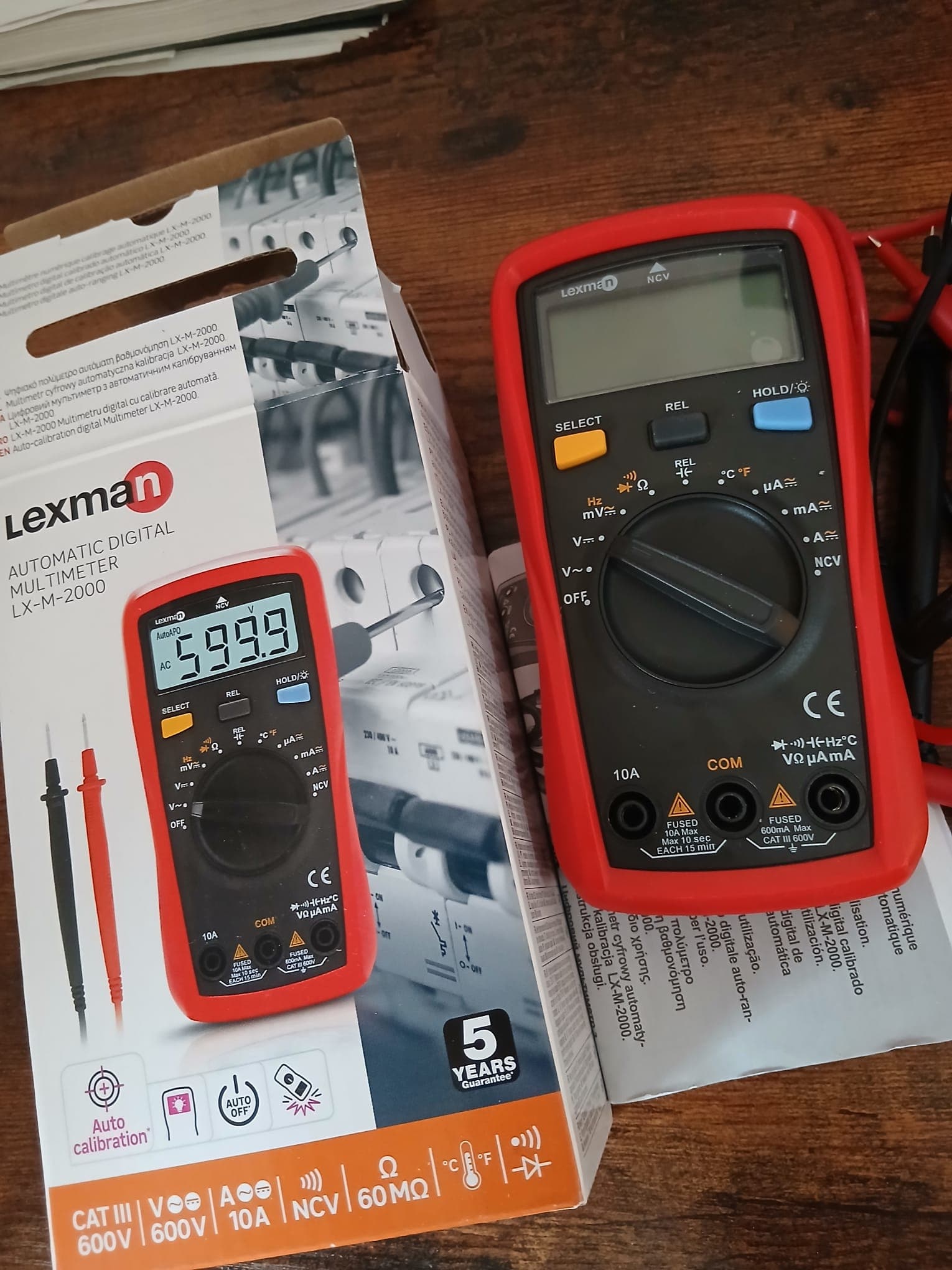
I bought a multimeter that measures voltage, resistance, and direct current up
to 10 A. How do you use it? The black probe goes in the COM socket, while for
voltage and resistance the red probe goes in the VΩmA socket.
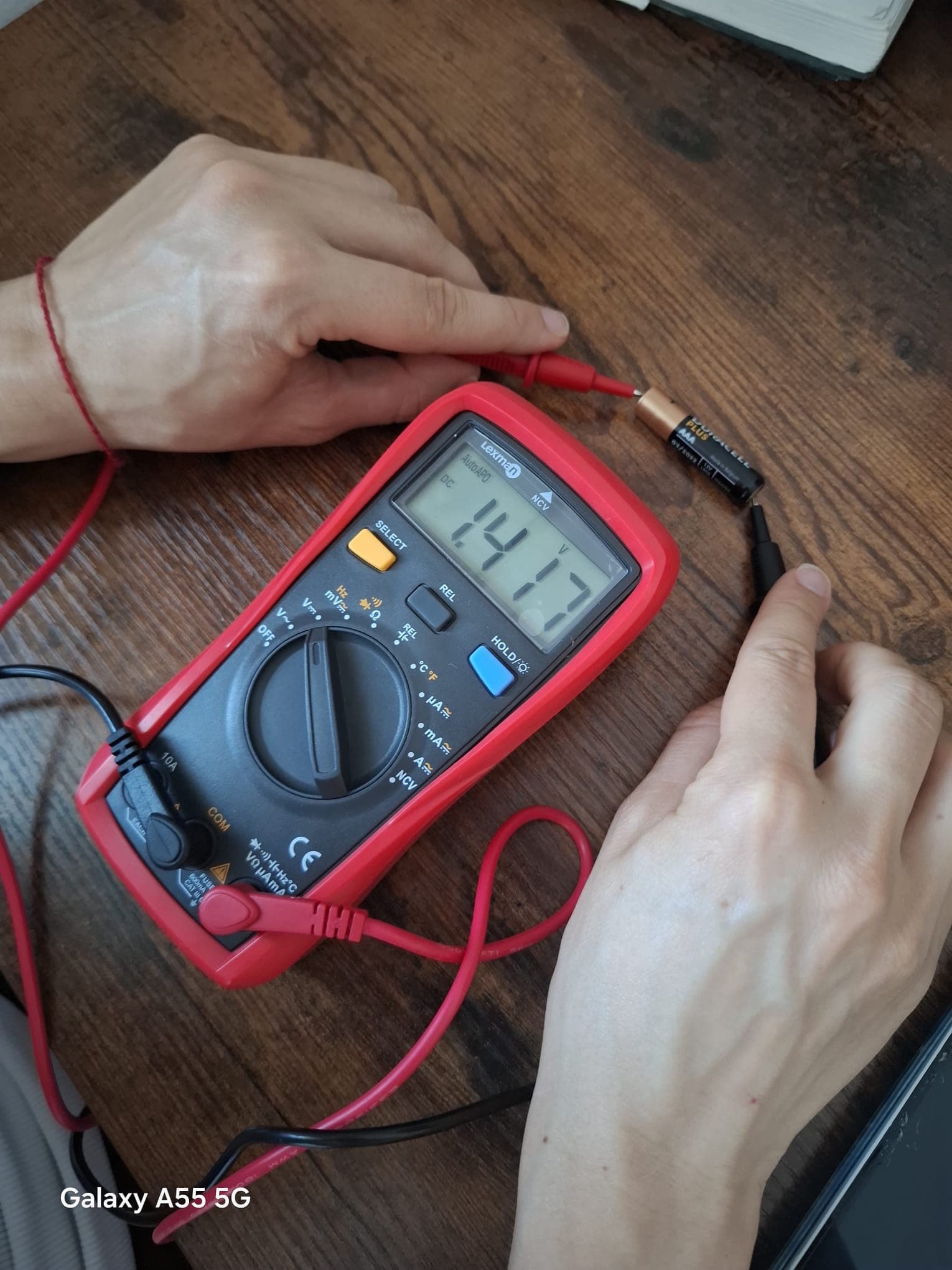
To learn how to use it I wanted to measure how flat the battery in my television remote was. It is a AAA cell and, with the red probe on the positive end and the black one on the negative end, the multimeter read about 1.4 V, a plausible value for a battery that has been in use for a while.
Checking the Wemos voltages
Now that I understood how it works, I moved on to the voltage supplied by the
Wemos regulator, with the red probe on the 3V3 pin and the black one on GND.
The multimeter showed 3.30 V, the value printed on the board.
Voltage is a potential difference, so when I measure the supply voltage of the
Wemos I compare the pin I care about, 3V3 in this case, with the ground, that
is GND.
I then measured the power bank voltage with the black probe on GND and the red
one on VIN, the USB power input. I read about 4.80 V, close to the 5 V
printed on the power bank.
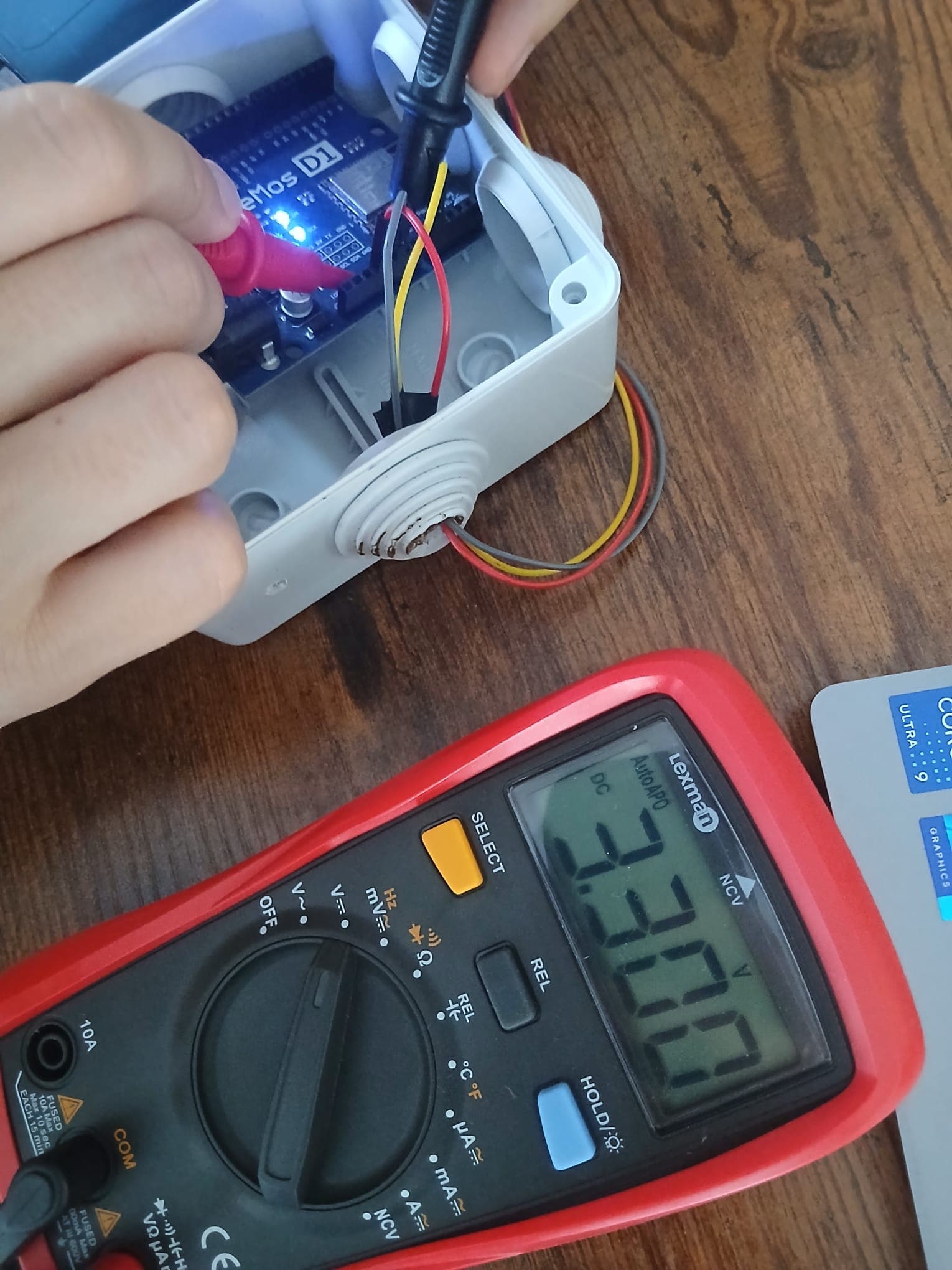
3V3 and GND: the multimeter reads 3.30 V.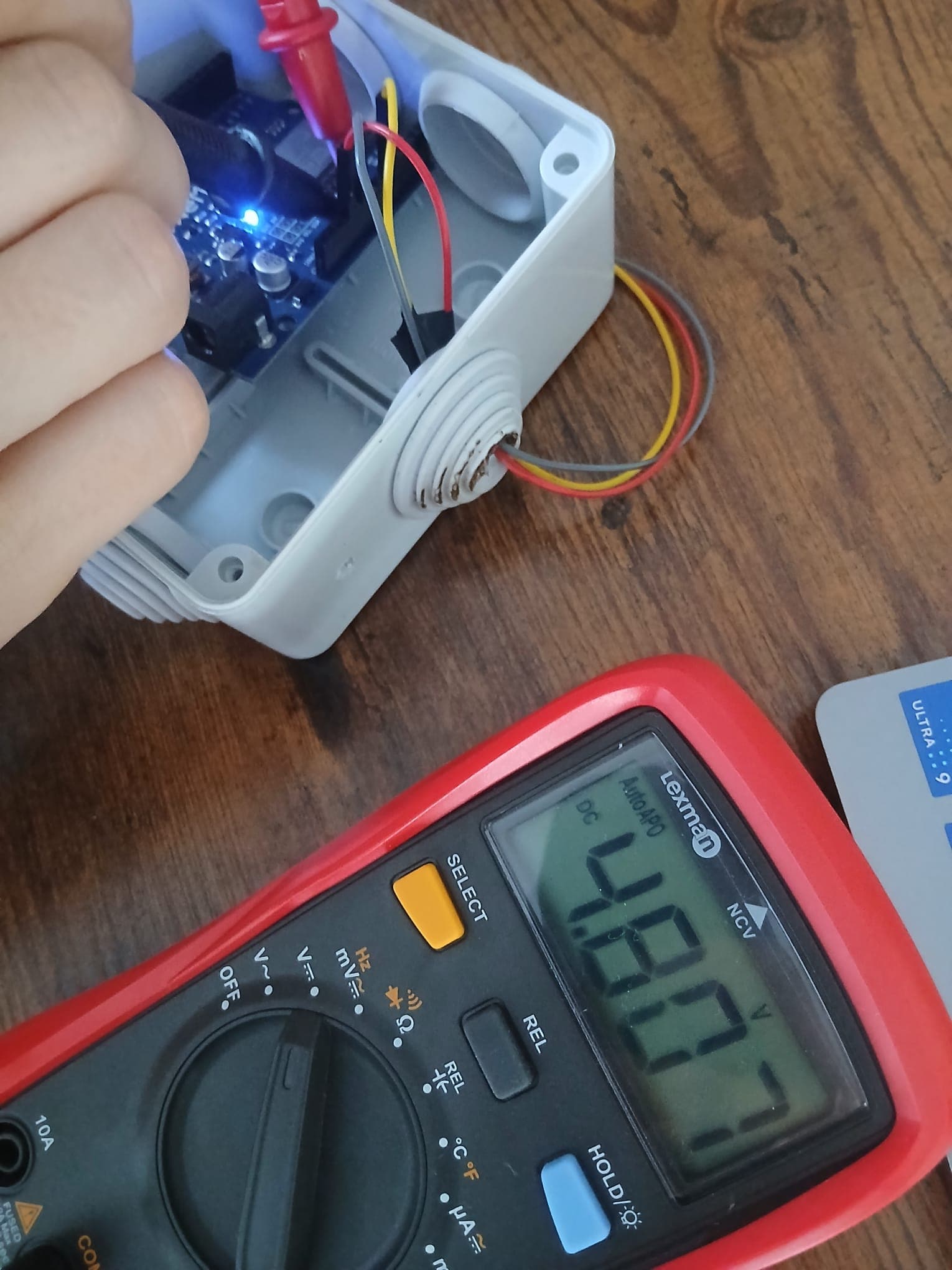
VIN, the input fed by the power bank.These results did confirm what the devices claim, but they also let me get to know the instruments I would need for the next step, measuring the active cycle.
Measuring the active cycle
At this point, as I said, we move on to measuring the active cycle, and therefore the firmware.
To measure the consumption more precisely I needed a USB power meter.
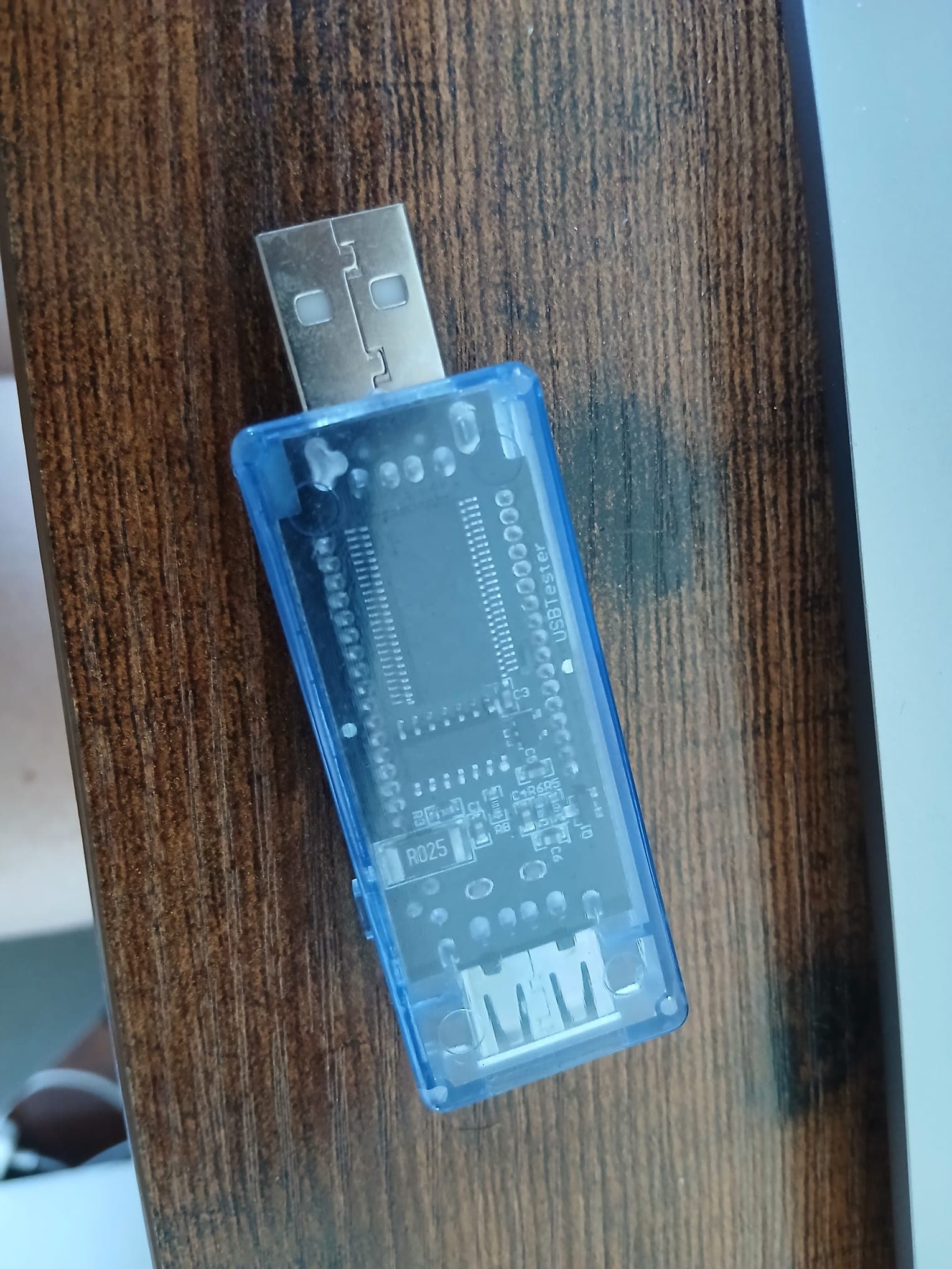
As you can see it has the shape of a memory stick, but it carries a display that shows the current drawn and the voltage.
This step took me two rounds:
- meter between the power bank and the Wemos;
- meter between the laptop and the Wemos.
In the first round, as soon as the parts were connected and the firmware started, the current and the voltage were 70 mA and 5.09 V. During deep sleep, though, everything switched off. My hypothesis is that the Wemos draws so little that either the power bank cannot keep feeding it or the meter cannot detect it.
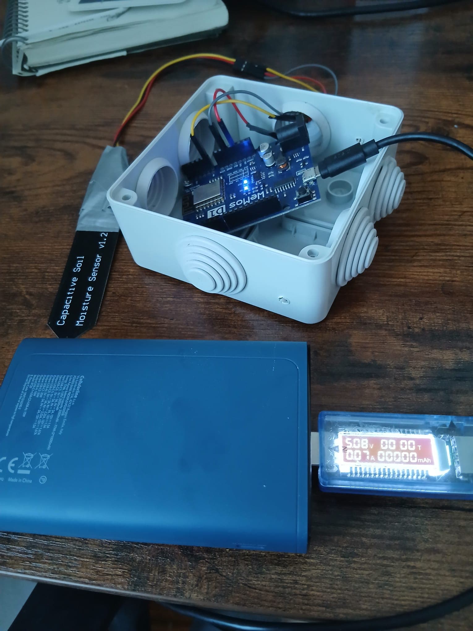
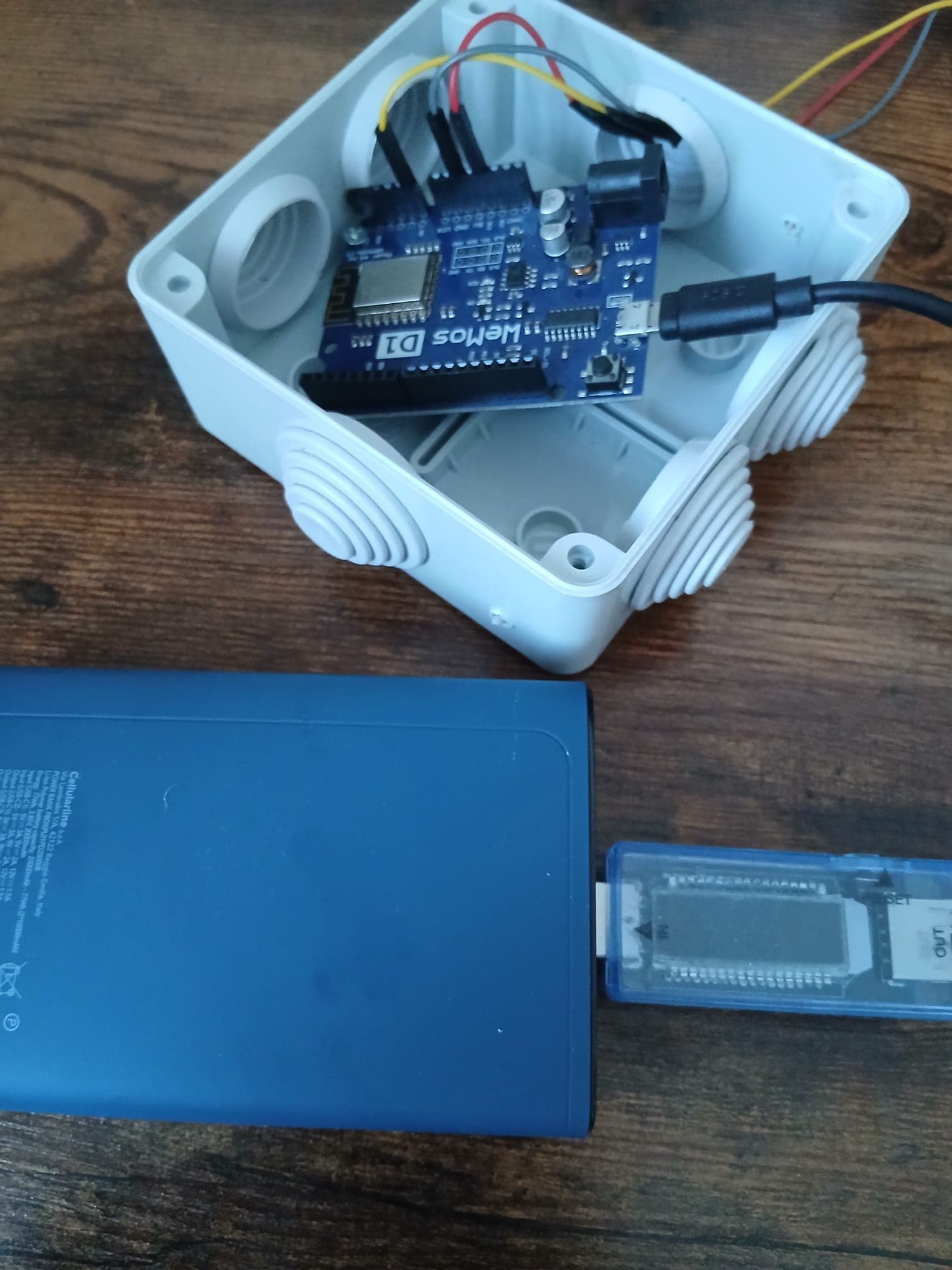
The second round gave me the same results, with one difference: this time the meter did not switch off, it simply showed a current of zero.
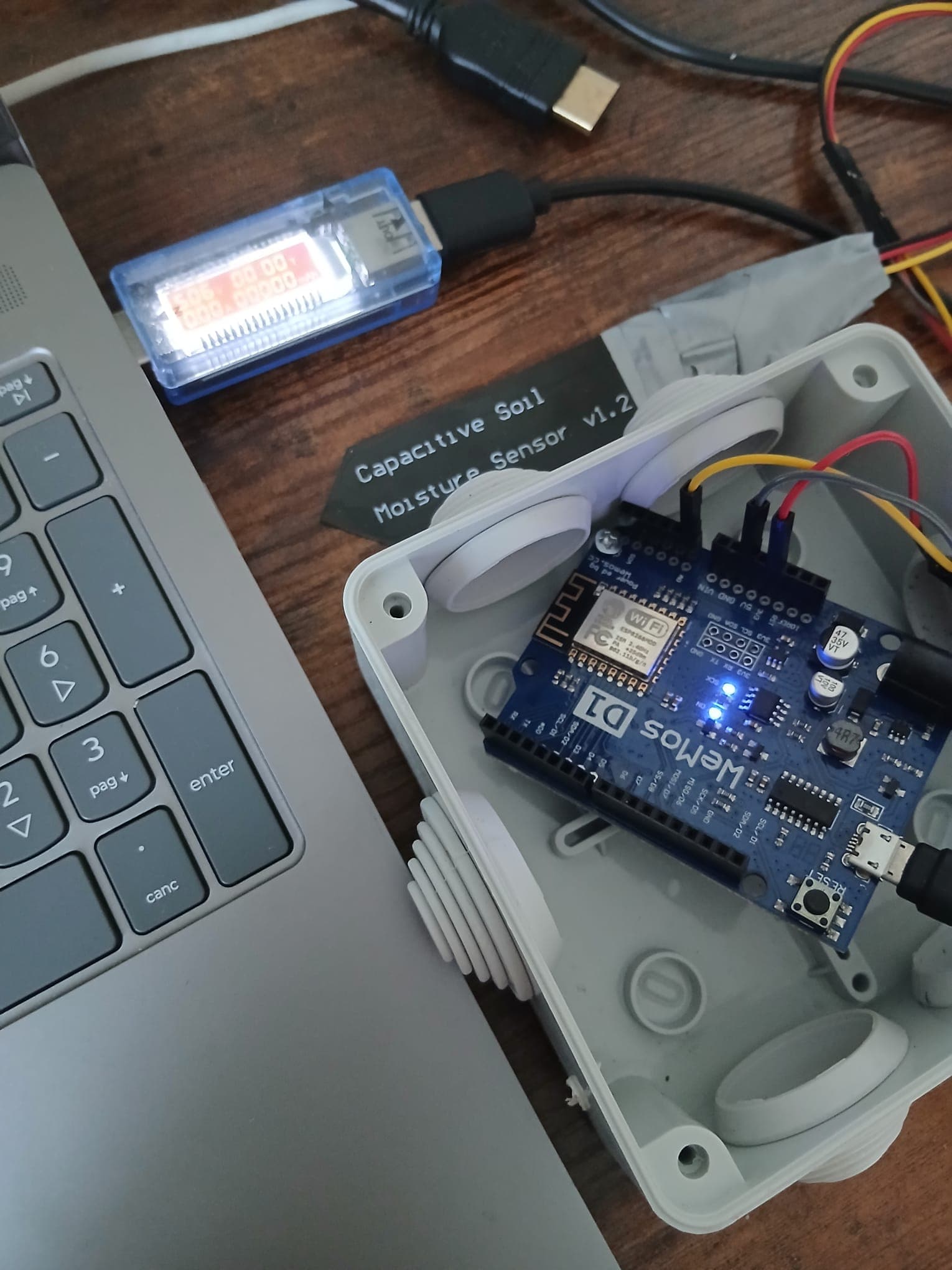
Finally, by adding some logging to the firmware, I recorded about 4334 ms for the Wi-Fi connection, 125 ms for the HTTP connection, and 4575 ms for the whole cycle. I then rounded everything to 5 seconds of active cycle, that is the duration of the entire firmware run.
Working out the daily consumption
Five seconds are about 0.00139 hours. One cycle therefore uses:
0.07 A × 0.00139 h = 0.000097 Ah
                         = 0.097 mAh
With two cycles per day:
0.097 mAh × 2 = 0.194 mAh per day
In deep sleep the meter could not read the current, so I used a value found online, about 0.15 mA:
0.15 mA × 24 h = 3.6 mAh per day
The total comes to about 3.8 mAh per day.

Written by Giulia Guglielmi
Notes on electronics, IoT, and software.