Updated 6 min
Powering My Wemos Soil-Moisture Sensor with Solar Energy
How I chose the battery, the solar panel, the charging module, and the step-up converter to make my Wemos sensor self-sufficient.
After building my Wemos soil-moisture sensor, I wanted to make it independent from the laptop and from the mains. In this short article I go through the components I chose, with a little of the reasoning behind them. For the instruments that helped me at this stage, you can read it alongside the tools I used to measure what the Wemos consumes.
Before choosing the components, though, I had to work out how much the Wemos consumes. That means working out what the firmware uses, first for a single cycle and then for a whole week.
Daily consumption
When the Wemos connects, the current rises to about 0.07 A, that is 70 mA. The Wemos is powered at 5 V from the USB input and the firmware takes about 5 seconds to run.
Five seconds are 0.00139 hours, so one cycle uses:
0.07 A × 0.00139 h = 0.000097 Ah
                         = 0.097 mAh
Counting two cycles per day, the calculation becomes:
0.097 mAh × 2 = 0.194 mAh per day
To get to this result I bought a small USB power meter. It looks a lot like a memory stick, but it can work out the voltage and the current a component draws.
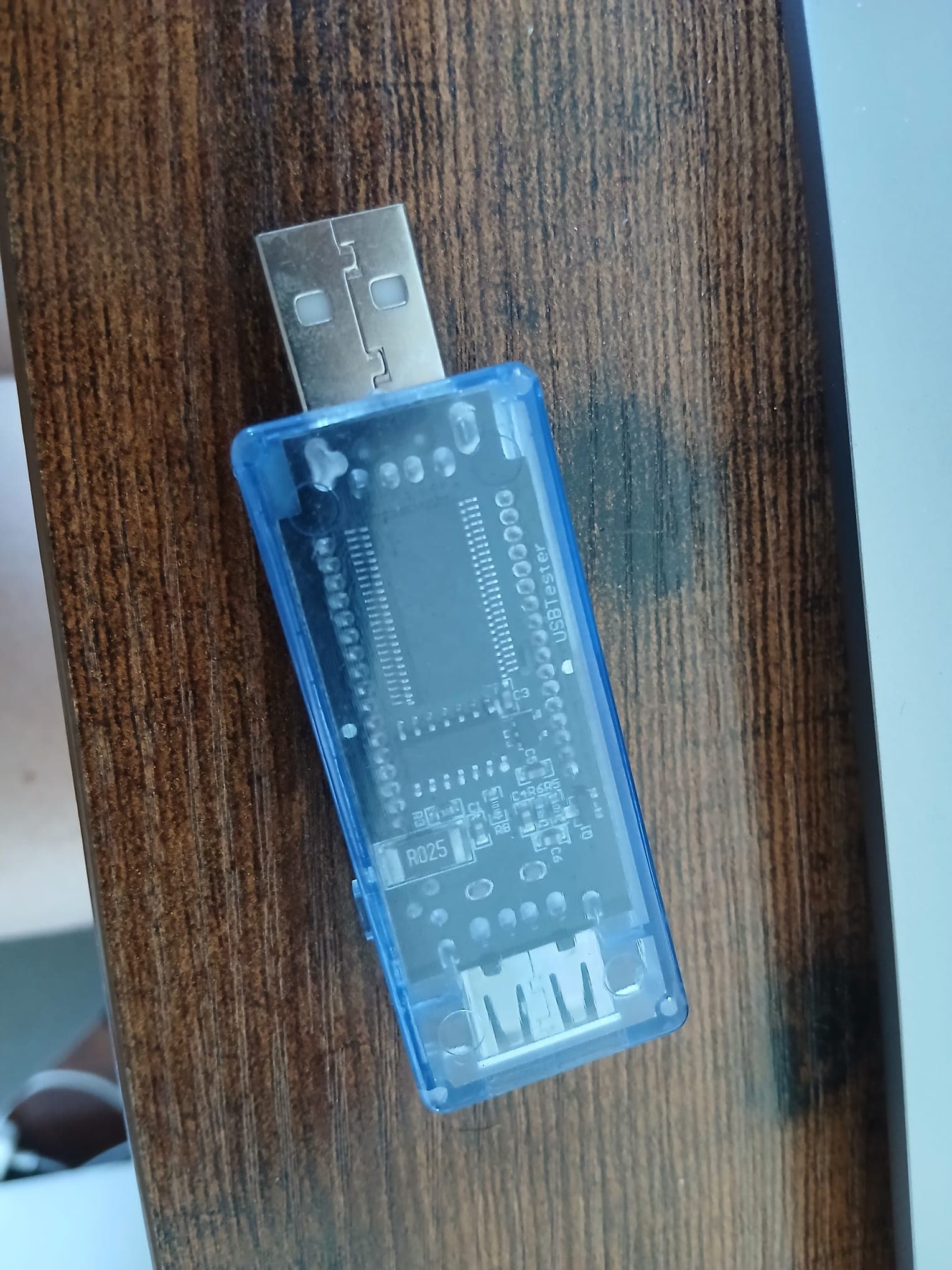
As for deep sleep, the meter could not work out the current, so I looked online and went with an estimate of about 0.15 mA, which brings the daily figure to 3.6 mAh:
0.15 mA × 24 h = 3.6 mAh per day
Adding deep sleep to the two active cycles, I get an estimate of about 3.8 mAh per day.
Those 3.8 mAh, however, are measured on the 5 V side, the USB input, while the battery has a nominal voltage of about 3.7 V. Milliamp-hours on the two sides cannot be compared directly, so I go through energy:
3.8 mAh × 5 V / 1000 = 0.019 Wh per day
Assuming a step-up converter efficiency of 90%, the charge the battery has to provide every day becomes:
0.019 Wh / 0.90 / 3.7 V × 1000 = 5.7 mAh per day
Energy planning
For a week the calculation becomes:
5.7 mAh × 7 days ≈ 40 mAh
I did not want a battery sized right at the limit, because there is less sun in winter, Wi-Fi creates current peaks, and a battery should not be fully discharged. To leave myself a margin I multiplied the result by ten:
40 mAh × 10 = 400 mAh
So I could have chosen a 1000 mAh battery, or one between 2600 and 3000 mAh. These batteries are not very common and are only sold in shops or websites that specialise in electronics. I live in Milan and found a very well stocked shop called Lady Elettronica.
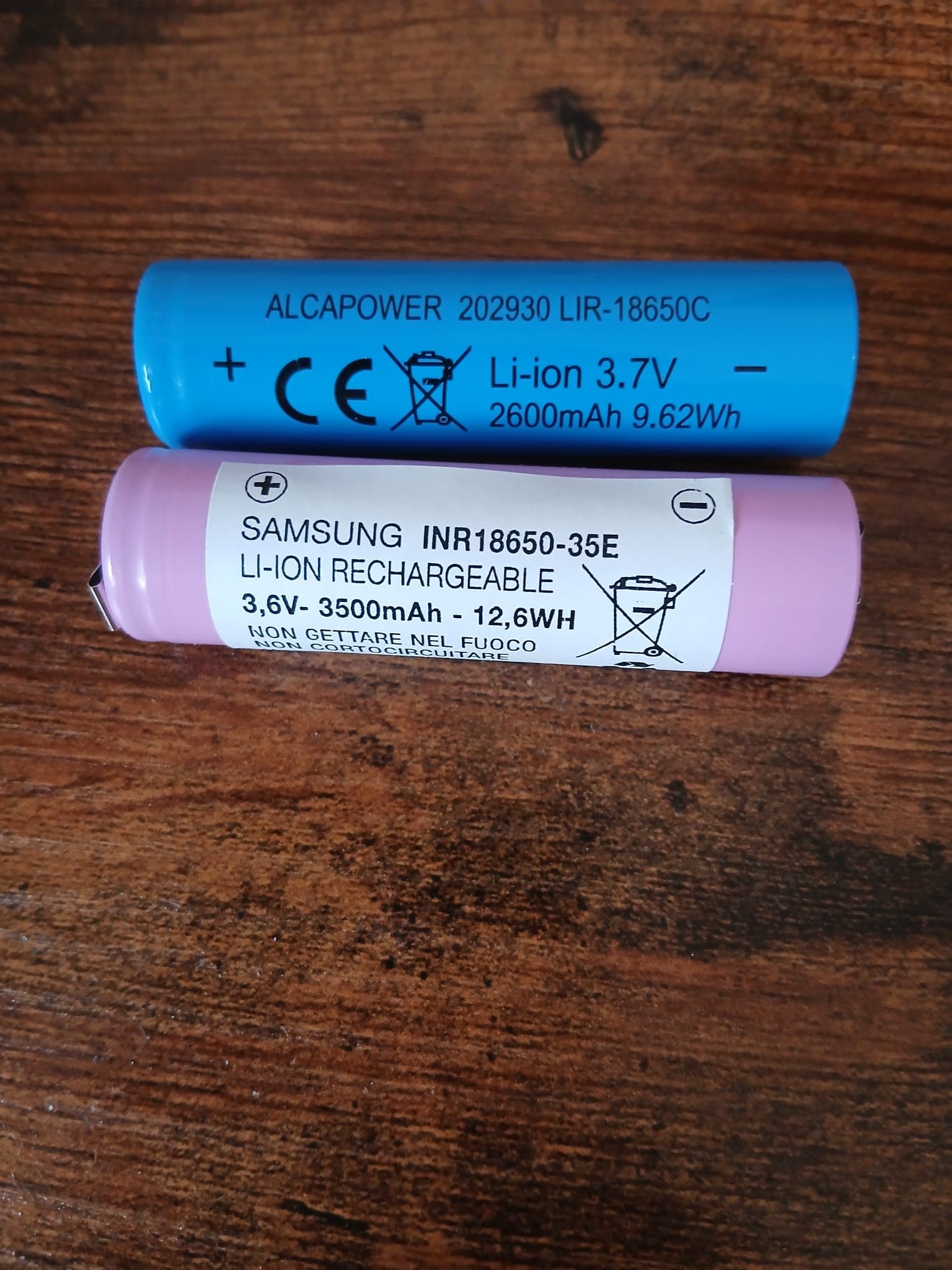
Here are the two batteries I decided to buy, 2600 mAh and 3500 mAh:
Choosing the battery
I chose the battery on three criteria:
- the voltage;
- the capacity;
- the maximum current it can provide.
The Wemos works at 3.3 V. For this reason I considered a single lithium-ion cell, that is a 1S battery, with a nominal voltage of 3.7 V and a maximum voltage, when fully charged, of 4.2 V.
The battery also has to cope with the Wi-Fi peaks, which can reach about 250 or 300 mA. So I decided on an 18650 of 3000 mAh, because it has a capacity well above the calculated minimum, a reasonable price, and a very common capacity in mAh. As I wrote above, though, the shop only had 2600 mAh and 3500 mAh cells and, since they can always come in useful, I bought both.
Choosing the solar panel
A solar panel produces power, so the choice is sized on the watt-hours it produces. I already converted the daily consumption into energy above, with the formula:
Wh = (mAh × V) / 1000
Where V is the voltage of the side on which I measured the current, that is
the 5 V of the USB input, and the result was 0.019 Wh per day.
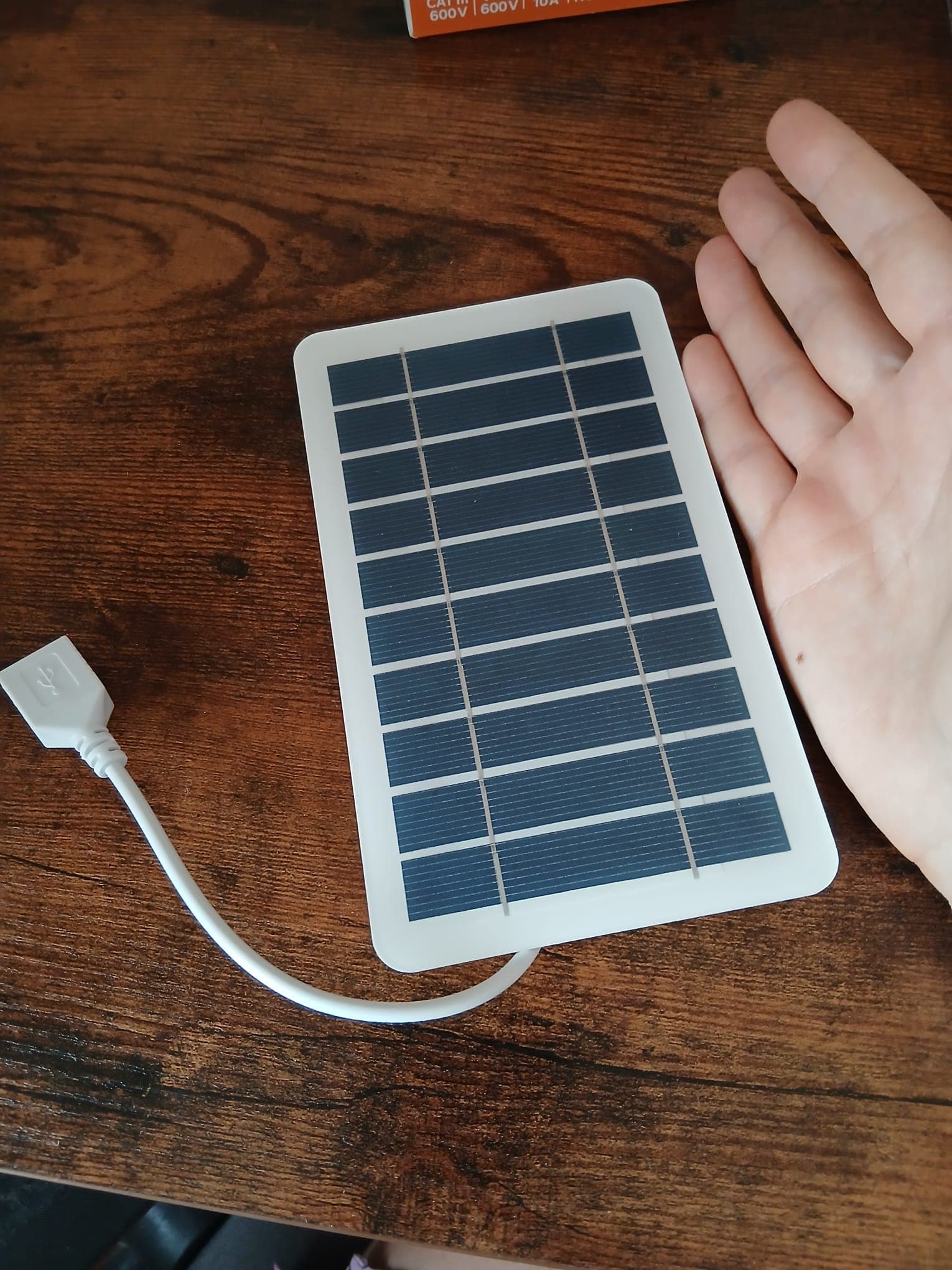
How much will my panel produce? My balcony faces east, so with a 2 W panel and about seven hours of sun I get 14 watt-hours:
2 W × 7 h = 14 Wh
The Wemos has to be fed at 5 V, which the step-up converter derives from the 3.7 V of the battery, and on the board the regulator then brings the voltage down to the 3.3 V of the logic. The charging module, on the other hand, wants an input of about 5 V, so I went for a 2 W, 5 V panel:
Charging module and step-up converter
The panel cannot be connected straight to the battery, because the battery could be overcharged, last less, or be damaged. So a charge management module is needed between the panel and the battery.
Without overthinking it I chose a TP4056 with USB-C, with DW01A and FS8205A protection against overcurrent and short circuit. The reason is that it is a module made for charging a lithium battery up to 4.2 V.
Finally, I had to take into account that the battery voltage falls as it discharges, while the Wemos needs a constant voltage. For this I added a step-up converter, which brings the battery output to a stable 5 V.
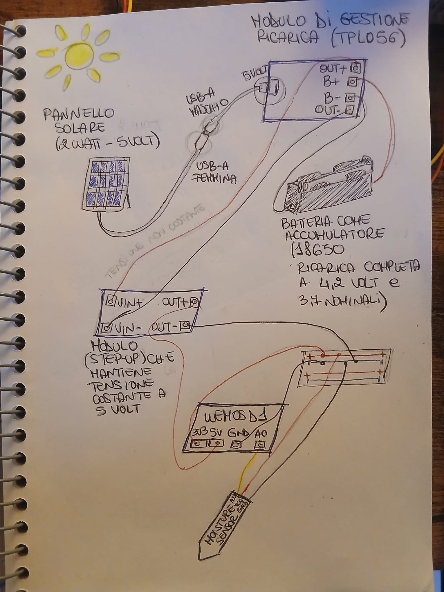
The image above is my own hand drawing of the path I had in mind, and it reads like this: the panel provides energy, the module manages the charging (to avoid overcharging our cell), the battery stores it, and the converter keeps the voltage that feeds the Wemos constant.
sun → solar panel → charging module → battery
    → step-up converter at 5 V → Wemos → moisture sensor

Written by Giulia Guglielmi
Notes on electronics, IoT, and software.